Reviewing Industry 4.0 as an Enabler for Sustainable Manufacturing

Hello! My name is Allison Spring and I am a rising Junior at Northwestern University studying Environmental Engineering. This summer, I have been working collaboratively with Filippo Ferraresi and Faith John with guidance from Jennifer Dunn, Santanu Chaudhuri, and Jakob Elias to write a literature review on technology and innovations in the area of Sustainable Manufacturing and to complete a data science project. Independent of the literature review, the goal of the data science project is to train a neural network to segment fiber and air particles in Nano CT images of N95 respirators.

Sustainable Manufacturing

Due to the importance of the environmental, economic, and ethical dimensions of sustainability, a lot of research has been performed in the field of Sustainable Manufacturing. After becoming more familiar with previous literature reviews, we identified three research areas to address within the field of Sustainable Manufacturing: Material and Fuel Substitution, Industry 4.0, and Additive Manufacturing. By creating a literature review, we seek to highlight the intersections between these areas and other green and lean manufacturing practices, expose gaps in the existing literature and identify areas for future research.

Industry 4.0

By implementing existing technologies within manufacturing processes, some estimates suggest that energy consumption across the sector could be reduced by 18-26% and CO2 emissions by 19-32%. The integration of these technologies would be so revolutionary that the concept is aptly named Industry 4.0-the Forth Industrial Revolution. Figure 1 below summarizes the technological developments that have advanced manufacturing to each new paradigm.

Figure 1: Defining Enablers of the past three phases of industry and Industry 4.0 (Tesch da Silva, F. S., da Costa, C. A., Paredes Crovato, C. D., & da Rosa Righi, R. (2020). Looking at energy through the lens of Industry 4.0: A systematic literature review of concerns and challenges. In Computers and Industrial Engineering (Vol. 143, p. 106426). Elsevier Ltd. https://doi.org/10.1016/j.cie.2020.106426)

Smart Manufacturing with Industry 4.0

A lot of technologies are encompassed by Industry 4.0 including those related to Artificial Intelligence, the Internet of Things (IoT) and Cyber-Physical Systems (CPS). These technologies along with others can be applied to various levels and processes in manufacturing to predict conditions, monitor operations, and make real-time informed decisions to optimize performance or efficiency. One example of how these multiple capacities can be leveraged is for maintenance. Through simulations based on data collected with sensors connected via the Industrial Internet of Things and Cyber-Physical Systems, the wear on machining tools can be predicted. This insight into the level of wear on machining tools is valuable because replacing and repairing machining tools can, for example, improve energy efficiency and decrease the amount of waste that is created. Moreover, understanding the relationship between wear, processing conditions, and performance presents an opportunity to optimize the life of machining tools which makes these systems more sustainable.

Furthermore, while there were case studies found during the literature search that demonstrate how these feedback loops can be integrated within existing manufacturing processes, other theoretical research suggests that Industry 4.0 could contribute to a massive paradigm shift in manufacturing processes. Research on the concept of Biologicalization or biological transformation in manufacturing suggests that in the future, Industry 4.0 could allow industrial machines to imitate biological processes such as healing, calibration, and adaptation. In the analogy created by Byrne et al. between artificial and natural systems, the Internet of Things functions as the nervous system by connecting sensors, processers, and automated feedback loops.

Pre- and Post-Consumer Logistics with Industry 4.0

 In addition to this influence over manufacturing processes, Industry 4.0 technology has also been used to inform sustainable product design and to establish more agile supply chains. To start, Artificial Intelligence was applied to product design in the aviation sector to calculate a sustainability score for proposed designs based on the processes required to manufacture the design and its life cycle. Big Data combined with Machine Learning, is also valuable in supply chains. One case study used these technologies to predict environmental and social risks within a supply chain to aid human decision making.

Moreover, more theoretical publications have also considered how Industry 4.0 could be employed during the transition to a more circular economy through Reverse Logistics which considers the supply chain infrastructure that would be required to “close the loop” as shown in Figure 2. Some of the general challenges of implementing a circular economy that could be approached using Industry 4.0 include minimizing costs, waiting times, and energy consumption during remanufacturing and recycling processes.

Figure 2: Reverse Logistics to close the Loop for a Circular Economy (The Importance of Reverse Logistics in Your Supply Chain. (n.d.). Retrieved August 13, 2020, from https://www.newcastlesys.com/blog/the-importance-of-reverse-logistics-in-your-supply-chain)

Conclusion

The next step in my research is to analyze the relationship between case studies that demonstrate how manufacturing can be retrofitted with Industry 4.0 and more theoretical papers that suggest a proactive integration of Industry 4.0 into manufacturing processes. From this process, I hope to understand the trajectory and the end-state model for Industry 4.0 as well as areas where additional research is needed to support this transition.

I have really enjoyed learning more about Sustainable Manufacturing and the significance Industry 4.0 could have on manufacturing and beyond. If you, too want to learn more about this research, look out for new entries by Filippo Ferraresi and Faith John about other innovative areas in Sustainable Manufacturing!

References

Fu, Y., Kok, R. A. W., Dankbaar, B., Ligthart, P. E. M., & van Riel, A. C. R. (2018). Factors affecting sustainable process technology adoption: A systematic literature review. In Journal of Cleaner Production (Vol. 205, pp. 226–251). Elsevier Ltd. https://doi.org/10.1016/j.jclepro.2018.08.268

Tesch da Silva, F. S., da Costa, C. A., Paredes Crovato, C. D., & da Rosa Righi, R. (2020). Looking at energy through the lens of Industry 4.0: A systematic literature review of concerns and challenges. In Computers and Industrial Engineering (Vol. 143, p. 106426). Elsevier Ltd. https://doi.org/10.1016/j.cie.2020.106426

The Importance of Reverse Logistics in Your Supply Chain. (n.d.). Retrieved August 13, 2020, from https://www.newcastlesys.com/blog/the-importance-of-reverse-logistics-in-your-supply-chain

Implementing an Automated Robotic System into an AI-Guided Laboratory

Hi! My name is Sam Woerdeman, and I am a rising senior at Northwestern University, pursuing a bachelor’s degree in mechanical engineering. Through the quarantine summer of 2020, I have been working with researchers Jie Xu and Dr. Young Soo Park in implementing an automated robotic system into a nanomaterial solution-processing platform. Although I have been working remotely from home, with the help of my mentors, I have been able to conduct research nonetheless, including the simulating, programming and controlling of a robot.

Significance of Automating Nanomaterial Production

Before I dive into the importance of the robotic system, I want to acknowledge the significance of automating nanomaterial production using an AI-guided, robotic platform. For one, we would be able to understand the multi-dimensional relationships of numerous properties resulting from the production of nanomaterials and thin films. Also, we could quickly identify and improve upon the workflow of producing nanomaterials. Finally, this system would allow us to reduce human error resulting from basic intuition and reproducing the material continuously.

Differentiation from the Available Autonomous Platforms

There are a number of key elements that separate my research in implementing the robotic system from past, competing projects. Primarily, it is uncommon to mimic an entire nanomaterial laboratory autonomously. Usually, small parts of the workflow are automated and then assembled, or larger scale materials are produced autonomously. Distinctively, I am working on a modular robotic system rather than a fixed workflow. This is essential because it allows researchers to easily adjust the workflow program, rather than having to construct a unique platform for each individual solution-processing experiment. This aspect allows the programming module to be used on projects for years to come.

Approach to Implementing the Robotic System

The goal of the project is to integrate an automated robotic system into the entire solution-processing platform; I approached it from three unique angles. First, the robot has to be modeled and simulated. By utilizing CAD parts, I was able to assemble a laboratory workspace that resembles the set-up in the Argonne laboratory. The completed CAD files were imported into a simulator program called CoppeliaSim, which provides a platform for adding joints and features to allow the robot to move and interact with its environment. I want to note the importance of creating a simulator as it allows us to experiment first with different commands instead of initially risking the expensive hardware of the actual robotic system and potentially wasting time and money.

Secondly, I programmed modules for the workflow using Python as the primary programming language. In order to connect the code directly to the simulator, I used a remote API connection. An API, which is an acronym for application programming interface, allows and defines interactions between multiple software. In my case, it allows me to control the robot simulator in CoppeliaSim using Python code. By simply importing the CoppeliaSim library, I can use the functions to control the simulator and create new functions with more complex commands. Mainly, the kinematics of the robot is showcased by manipulating the motion of the joints, inputting different Cartesian coordinates for the robot to follow, and control the speed and acceleration of the robotic arm.

Example of how the joint motion function operates

Finally, I look to control the robot using my Python programming modules and simulator. While I am completing my internship remotely, the show must go on. Therefore, my mentors and I were able to remotely control the robot, which is located at our vendor’s laboratory. We did this by video chatting and connecting to the vendor’s computer using Chrome Remote Desktop. We inputted Python code, watched the simulation, and observed the robot completing the corresponding commands all from our homes. Even though we did not intend for the project to be remote, this gave us the confidence that we can control these systems from all over the world without wasting valuable time.

Remote connection of the robot using Python code and simulator simultaneously

Overall, I am amazed that I have been able to accomplish all of this in eight weeks thus far in the NAISE program, especially when considering that I am a mechanical engineering major who came into the project expecting to manually run trials with the robotic system. None of this would be possible without my mentors’, Jie Xu’s and Young Soo Park’s, assistance as well as Dr. Jennifer Dunn and Britanni Williams for keeping the NAISE program running in these strenuous times. In the coming weeks, I look to finish the library of functions for the simulator, demonstrate a basic workflow on the simulator and robot, and ultimately merge my robotic system with the artificial intelligence aspect of the project.

References

MacLeod, B.P. “Self-driving laboratory for accelerated discovery of thin-film materials” Science Advances. May 13, 2020

Social Distancing Detection

Hello there! My name is Ori Zur and I am a rising junior at Northwestern University studying computer science and music composition. This summer at Argonne, I sought to answer the following question: how well are people following social distancing guidelines in outdoor urban environments?

For the past six months, the world has been enduring a historic pandemic due to the COVID-19 virus. As society attempts to adjust to the new lifestyle of mask wearing, virtual education, and working from home, one phrase that constantly gets brought up is “social distancing guidelines.” Social distancing is the action of keeping a distance of at least six feet from others in order to reduce the spread of the Coronavirus disease. For the past two months, I’ve been designing and coding a social distancing detector using Python and OpenCV as a means to answer the question of what percentage of people are properly following these social distancing guidelines.

The program takes a video of pedestrians, typically from surveillance camera footage, and analyzes each frame by detecting the people, calculating the distance between each pair of people, and indicating if any two people are standing less than six feet apart. OpenCV, a computer vision function library, was used because it greatly simplifies the process of loading in a video, separating it into individual frames for analysis and editing, and outputting the final results.

How It Works

There are two main components to the program: the setup, which only occurs once in the beginning, and the operation, which is a loop that occurs once for each frame of the input video.

The Setup

When the program begins running, the first frame of the input video is shown to the user. The user then inputs six points with their mouse. The first four points make up a rectangle on the ground plane, which will be referred to as the “region of interest” or ROI. The last two points are an approximation of a six-foot distance on the ground.

Six mouse points inputed by the user on the first frame of the input video. The four blue points make up the region of interest and the two green points are the six-foot approximation. Here, the height of the person was used to approximate six feet, but ideally there would be markers on the ground to help guide the user in plotting these points.

The purpose of creating a region of interest with the first four mouse points is to solve the issue of camera distortion. Because the camera is filming from an angle, the conversion rate between physical distance on the ground and pixel distance in the image is not constant. In order to solve this problem, the four mouse points are used to warp the region of interest to create a bird’s-eye-view image. This new image, shown below, looks distorted and unclear, but its appearance is irrelevant as it won’t be shown to the user. What’s important is that in the warped image, the conversion rate between physical distance and pixel distance is now constant.

Original Image
Warped Bird’s Eye View Image

In order to prove that this works, I created a small-scale experiment using LEGOs and ran the image through the same warping function. On the left, the tick marks on the sides of the paper are not evenly spaced in terms of pixel distance due to the camera angle. On the right image, however, the tick marks on the side of the paper are evenly spaced, indicating that the physical distance to pixel distance conversion rate is now constant.

Left: original image, four blue points are inputed by the user via mouse clicks.
Right: result of image transformation.

The last part of setup is to use the last two inputted mouse points to calculate the number of pixels that make up six feet. The coordinates of these two points are warped using the same function used to warp the image, and the distance formula is used to calculate the number of pixels between them. This distance is the number of pixels that make up six feet, which I call the minimum safe distance, and since the points and image were warped using the same function, this pixel distance is the same throughout the entire bird’s-eye-view image.

The Operation

The first step of the operation loop is person detection, which is accomplished using a real-time object detection program called You Only Look Once, or YOLO. This program recognizes a wide variety of objects, but my program includes a filter that only keeps the person recognitions. Once detection occurs, each person is represented by what’s called a “bounding box,” which is a rectangle whose coordinates surround the person.

The next step is to take a single point from each bounding box, warp it using the same function used in the setup, and map the coordinates of the warped box points onto the bird’s-eye-view image. Because everything is now mapped onto the bird’s-eye-view image, the distance formula can be used to calculate the distances between each pair of points. These distances are then compared to the minimum safe distance which was also calculated in the setup.

The final step is to create and display the outputs for the current frame. The first output is the street view, where red and green rectangles are drawn on the bounding boxes of the detected people. The second output is a representation of the bird’s-eye-view image using a white window and green and red circles to represent the warped box coordinates that were mapped in the previous step. Once the outputs are displayed, the loop moves onto the next frame of the input video.

Screenshot of the program in action.
Left: bird’s-eye-view output
Right: street view output

Here is a flowchart that summarizes the steps of the setup and operation components of the program.

Setup steps are in orange and operation steps are in green.

Next Steps

One feature that I plan to add to the program in my remaining time at Argonne is the ability to detect groups of people walking together. For example, a couple or family walking together may be less than six feet apart, but that should not be considered a violation of social distancing guidelines. This will be done by adding in an algorithm that can associate objects across multiple frames and assign unique IDs to each person detected. Using this algorithm, my program will be able to recognize groups of people walking together by tracking their specific object IDs, and disregard them as violators even if they are standing too close together.

References

  1. https://github.com/deepak112/Social-Distancing-AI
  2. https://github.com/aqeelanwar/SocialDistancingAI
  3. https://www.pyimagesearch.com/2020/06/01/opencv-social-distancing-detector/
  4. https://www.pyimagesearch.com/2014/08/25/4-point-opencv-getperspective-transform-example/
  5. https://www.pyimagesearch.com/2018/11/12/yolo-object-detection-with-opencv/

Automatic Wildfire Smoke Detection Using Deep Learning

Hi friendly reader! My name is Aristana Scourtas, and I’m currently pursuing my MS in Artificial Intelligence at Northwestern University. I have two years of industry software experience and a dream to apply my computing skills to environmental and climate change-related issues. This summer I’m committed to finding novel solutions to an old problem — early detection of wildfires.

Fire moves fast

The early detection of smoke from wildfires is critical to saving lives, infrastructure, and the environment — and every minute counts. Once ignited, a fire can spread at speeds of up to around 14 mph1 — that’s about 2.3 miles every 10 minutes! The devastating Camp wildfire that tore through northern California in 2018 moved at more than a football field per second (160 ft/s) at its fastest point.2

The Camp Wildfire (Nov 8th, 2018), imaged via Landsat 8, a NASA/USGS satellite.3

So how can we do this? Currently, wildfires are detected any number of ways: in California, wildfires are typically first recorded via 911 (a US emergency hotline) calls4, but we also detect wildfires via fire watchtowers or by camera networks and satellite images (like from the GOES5 or VIIRS6 satellites) that inspect areas of interest. In all of these cases, a person needs to continually monitor the data streams for signs of smoke and fires.

However, human beings can only do so much. Continuously monitoring multiple video feeds for fires is a fatiguing, error-prone task that would be challenging for any person.

But how about a computer?

What deep learning can do

Deep learning is a subset of machine learning that focuses specifically on neural networks with a high number of layers. Machine learning is really good at doing things humans are typically bad at, like rapidly synthesizing Gigabytes of data and finding complicated patterns and relationships.

A simple neural network with only one hidden layer. We’d call this a “shallow” neural network. (Graphic modified from V. Valkov)8

Neural networks are said to be “universal approximators”,7 because they can learn any nonlinear function between an input and an output — this is very helpful for analyzing the patterns and relationships in images, for example.

Deep learning algorithms are good for the task of smoke detection, because they can constantly and automatically “monitor” the image and video streams from fire watchtower networks and satellites, and alert officials when there’s likely smoke in the image.

Current algorithms

As I’m writing this article, the current research out there on deep learning for wildfire smoke detection largely focuses on using Convolutional Neural Networks (CNNs) for static images. CNNs are commonly used for image data, and are good at learning spatial information.

For example, in my smoke detection research, we’re working with an image dataset from the HPWREN9 tower network in southern California.

An example HPWREN image capturing smoke. This image, after it is pre-processed for the neural network, is then fed to the CNN as input.

Unfortunately, while these CNN-based algorithms usually have high accuracy, they can also produce a high number of false positives, meaning they mistake other things, like clouds or fog, for smoke.

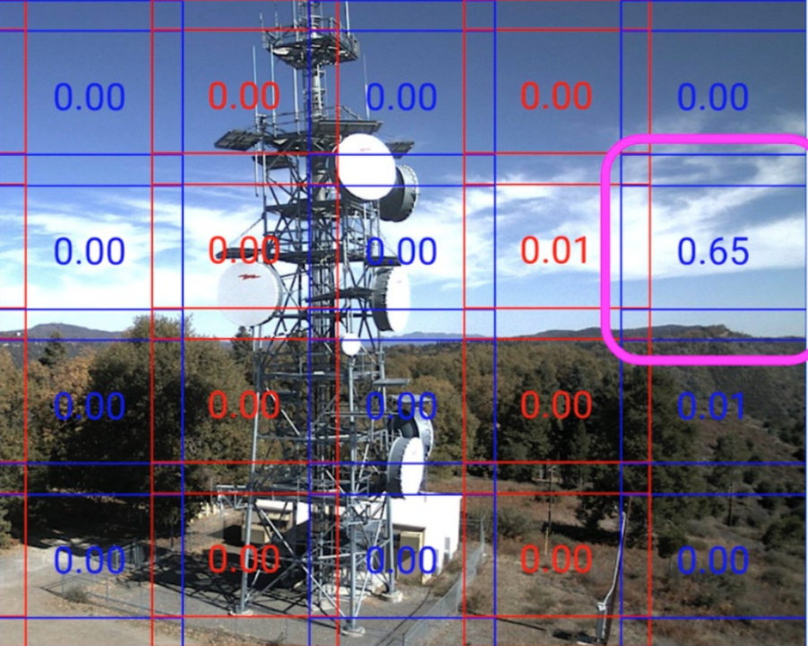
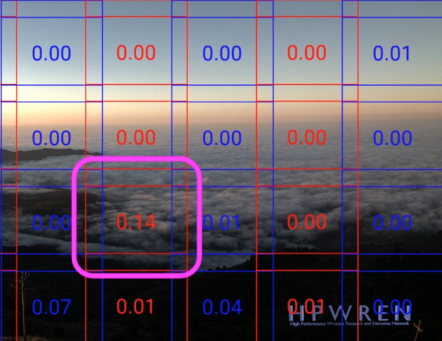
Examples of false positives from the work of Govil et al in their 2020 paper. This model divided the image into a grid, and assigned the likelihood of each grid cell being smoke (the threshold for smoke was adjusted dynamically).4 On the left, clouds were mistaken for smoke. On the right, fog was mistaken for smoke.

Furthermore, while these models do well in their studies, oftentimes they do not perform well when assessed with images from other regions. For instance, the ForestWatch model, which has been deployed in a variety of countries such as South Africa, Slovakia, and the USA, did not perform well when assessed using data from Australian watch towers.10

This begged the question: “well, how do humans detect wildfire smoke?” Looking through the dataset of images of California landscapes, I often found I could not tell if there was smoke in any of the early images.

Can you find the smoke in this image from the HPWREN towers? It was taken 9 minutes after the smoke plume was confirmed to be visible from the tower.
(Answer: from the left of the image, it’s 1/3 of the way in)

I’d only see the smoke once I compared images sequentially, from one timestamp to the next. Intuitively, movement on or below the horizon seemed to be a key aspect of recognizing smoke.

Is time the secret ingredient?

After listening to the opinions of my mentors and a California fire marshal, it seemed like everyone agreed — movement was a key part of how we identified smoke.

Could we create a model that learns temporal information as well as spatial information? In other words, could it learn both what smoke looked like (spatial), and how the images of smoke changed over time (temporal)?

I’m now developing an algorithm that can do just that. Often, a Long Short-Term Memory network (LSTM), which is a kind of Recurrent Neural Network (RNN), are used for learning patterns over time (i.e. in sequential data). For instance, LSTMs are frequently used for text prediction and generation (like that in the Messages app on iPhones).

Models that combine spatial data (often learned via CNNs) with some other model or technique that captures temporal data have been used in a variety of other applications with video or sequential image data, such as person re-identification, object tracking, etc.

We’re exploring how we can apply a similar hybrid spatial-temporal model to our smoke dataset.

Conclusion

Automated early detection of wildfire smoke using deep learning models has shown promising results, but false positive rates remain high, particularly when the models are deployed to novel environments.

Including a temporal component may be a key way we can improve these models, and help them distinguish better between smoke and clouds or fog.

This work doesn’t come a moment too soon, as wildfires are increasing in intensity and frequency due to climate change’s effects on air temperature, humidity, and vegetation, among other factors. Unfortunately, fires like the ones that tore across Australia earlier this year will become much more common in many parts of the globe.

Hopefully, as we improve the technology to detect these fires early on, we can save lives and ecosystems!

The Amazon Rainforest, home to many peoples and countless species. A home worth protecting.

References

  1. “How Wildfires Work”. https://science.howstuffworks.com/nature/natural-disasters/wildfire.htm
  2. “Why the California wildfires are spreading so quickly”. https://www.cnn.com/2018/11/09/us/wildfires-why-they-spread-so-quickly-wcx/index.html
  3. Camp Fire photo. https://en.wikipedia.org/wiki/Camp_Fire_(2018)
  4. Govil, K., Welch, M. L., Ball, J. T., & Pennypacker, C. R. (2020). Preliminary Results from a Wildfire Detection System Using Deep Learning on Remote Camera Images. Remote Sensing12(1), 166. https://www.mdpi.com/2072-4292/12/1/166
  5. GOES. https://www.nasa.gov/content/goes-overview/index.html
  6. VIIRS. https://ncc.nesdis.noaa.gov/VIIRS/
  7. Scarselli, F., & Tsoi, A. C. (1998). Universal approximation using feedforward neural networks: A survey of some existing methods, and some new results. Neural networks11(1), 15-37. https://www.sciencedirect.com/science/article/pii/S089360809700097X?casa_token=NaZxQdSUi6MAAAAA:zMhRIkTNDTZWSWze5wIHVK73EtlgHzLm3cAMkRBpQmepxH3cSAyhIvPKpu_H5b-2kYdTcG1IQA
  8. NN graphic. https://towardsdatascience.com/build-a-simple-neural-network-with-tensorflow-js-d434a30fcb8
  9. HPWREN. http://hpwren.ucsd.edu/cameras/
  10. Alkhatib, A. A. (2014). A review on forest fire detection techniques. International Journal of Distributed Sensor Networks10(3), 597368. https://journals.sagepub.com/doi/full/10.1155/2014/597368
  11. Amazon Rainforest photo. https://www.telegraph.co.uk/travel/destinations/south-america/articles/the-amazon-travel-guide/

Applications-Oriented Review of Energy Storage

~5 MIN READ

Hello! My name is Alexia Popescu, and I am a rising sophomore in Materials Science & Engineering at Northwestern University. This summer I’ve enjoyed working with Lynn Trahey and George Crabtree under the Joint Center for Energy Science Research (JCESR). In my project, I am compiling an applications-oriented review of specific shortcomings and outlooks in energy storage systems, helping accelerate the emergence of next-generation technologies.

Energy storage is essentially any device that converts and keeps energy in an accessible form. Most familiar are batteries, storing energy through chemical reactions, but there are also many thermal, mechanical, and hydrogen-based technologies. Their scope goes beyond portable power for a phone, as each plays a part in the complex system which consumers, manufacturers, businesses, and governments rely on for on-demand energy. Furthermore, they are pivotal in the push towards reducing green-house gas emissions (decarbonization), coupling with cleaner energy sources like wind and solar renewables to make them more reliable and competitive.

While energy storage has experienced considerable growth, the pace of discovery is nonetheless too incremental to meet the urgency of market demand or the pace of climate change. Part of the challenge is that distinct applications of energy storage have significantly different target performance standards, so no one technology can meet the needs of every application. Another concern is that energy researchers are often divorced from the lessons learned from engineers who integrate and deploy energy storage systems.

Thus, my work aims to be a step forward in bridging the practical with the theoretical through a literature review. It does not intend to be an exhaustive survey reaching through every corner of the energy sector, but rather a perspective piece, highlighting tangible energy storage needs in major application areas. Much of my research so far has been looking at transportation.

In transportation, innovation might seem to have stabilized around lithium-ion batteries. That is primarily the case for short-distance light-road transport like passenger electric vehicles (EVs) where there are more than 326,400 battery-based electrics on U.S. roads today compared to only about 7,600 hydrogen fuel cell cars (DOE Alternative Fuels Data Center). Batteries tend to have higher efficiency, lower cost, and more availability of charging infrastructure thus making them more favorable in passenger cars than hydrogen fuel cells. However, the faster charge time and longer range of hydrogen-based storage is promising in heavy-road transport like buses and trucks, as illustrated in Figure 1.

Figure 1: An illustration showing how short-distance road transport may be best electrified by batteries, while long-distance favors hydrogen and in between, there are a range of other feasible options [1].

Road, rail, maritime, and aviation electrification are each at a different phase of emergence, as technical and commercial requirements dictate which energy storage systems best fit each sector’s needs. Due to the chemistry happening at the molecular-level, a battery generally can output large amounts of energy —having high specific power and power density— while a fuel cell is optimized for outputting energy for a longer time —having high specific energy and energy density. These performance “metrics” are just a few of those considered when comparing different technologies. Figure 2 is another comparison of metrics, in this instance between two main battery types.

Figure 2: A filled “spider” plot comparing the different performance and cost priorities of a battery A) for an EV and B) for storing solar or wind for the electric grid. The closer an endpoint is to the edge of the plot, the higher its value. [2]

Next steps for my work include exploring other areas such as the electrical grid in a similar application-metrics lens. Part of the process will be understanding the current role of energy storage in the grid and then diving deeper into the outlook for future developments. Exciting applications are on the horizon, such as renewables-sourced “green” hydrogen decarbonizing heavy industry and cutting-edge batteries and fuel cells enabling electric flight in designs like Figure 3. The result of this project will hopefully lay a foundation for a review of energy storage on the forefront of innovation.

Figure 3: The Bartini prototype of an electric vertical take-off and landing (eVTOL) aircraft that runs on hydrogen fuel cells. [3]

References:

1.         LePan, N. The Evolution of Hydrogen: From the Big Bang to Fuel Cells. 2019, April 13. [cited 2020, July 27]; Available from: https://www.visualcapitalist.com/evolution-of-hydrogen-fuel-cells/.

2.         Trahey, L., et al., Energy storage emerging: A perspective from the Joint Center for Energy Storage Research. Proceedings of the National Academy of Sciences, 2020. 117(23): p. 12550-12557.

3.         Bartini. The Future of Air Travel. 2020  [cited 2020, July 30]; Available from: https://bartini.aero/.

Computer Simulation of Photonic Quantum Networks

Greetings, my name is Alex Kolar and I’m a rising junior studying Computer Engineering at Northwestern University. This summer, I’ve been working with researchers Rajkumar Kettimuthu and Martin Suchara to develop and implement the Simulator of QUantum Network Communications (SeQUeNCe) to simulate the operation of large-scale quantum networks.
Quantum information networks operate in a similar manner to classical networks, transmitting information and communications between distant entities, but with the added ability to utilize principles of quantum mechanics in data encoding and transmission. These principles include supersposition, by which a single unit of quantum information (qubit) can exist in a probabilistic mixture of different states, and entanglement, by which multiple qubits are affected by actions on one qubit. Many applications are thus available for quantum networks including distribution of secure keys for encryption and reduction of complexity for distributed computing problems.
The simulator, in its current implementation, models the behavior of such networks at the single-photon level with picosecond resolution. This will allow us to test the behavior of complicated networks that cannot be tested without significant time and monetary investment or even within the confines of current optical technology.
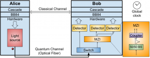
As a test of the simulator, we reproduced the results of an existing physical experiment (see references) to generate secure encryption keys. The simulated optical hardware is shown in Figure 1, where Alice generates the bits for the key and transfers these to Bob.

Figure 1: Quantum Key Distribution (QKD) setup

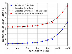
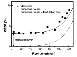
After constructing the keys, we measured the percentage of bits in the keys that differed between Alice and Bob (Figure 2) and compared these to the results of the experiment (Figure 3). Our measured error (blue squares) corresponds closely to the error predicted in the original experiment. We were also able to add a “phase error” to error rate (red diamonds) such that our results matched the experimental results.
Figure 2: Simulated QKD error rate

Figure 3: Experimental error rate results

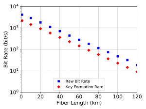
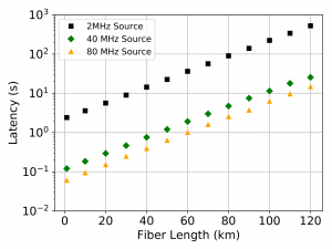
In continuing this simulation, we also were able to generate timing data on the rate of key formation (Figure 4) and latency of key formation (the time until the first key is generated – Figure 5). For the latency, this value was calculated with differing qubit generation frequency, showcasing the ability of the simulator to quickly produce results with varying parameters for its elements.
Figure 4: Simulated rate of key generation

Figure 5: Simulated Latency of key generation for varying qubit generation frequencies

As shown, SeQUeNCe allows for quick and accurate modeling of quantum communication networks. In the future, this will allow us to test increasingly complicated networks and develop new protocols for their real-world operation.
References:

C. Gobby, Z. Yuan, and A. Shields, “Quantum key distribution over 122 km of standard telecom fiber,” Applied Physics Letters, vol. 84, no. 19, pp. 3762–3764, 2004.

Using Computational Methods as an Alternative to Manual Image Segmentation

Hello! My name is Nicole Camburn and I am a rising senior studying Biomedical Engineering at Northwestern University. This summer I am working with Dr. Marta Garcia Martinez, Computational Scientist at Argonne National Laboratory, with the goal of using machine learning and learning-free methods to perform automatic segmentation of medical images. The ultimate objective is to avoid manually segmenting large datasets (a time consuming and tedious process) in order to perform calculations and generate 3D reconstructions. Furthermore, the ability to automatically segment all of the bone and muscle in the upper arm would allow for targeted rehabilitation therapies to be designed based on structural features.
This past year, I did research with Dr. Wendy Murray at Shirley Ryan AbilityLab, and I was looking at how inter-limb differences in stroke patients compared to healthy patients. Previous work done in Dr. Murray’s laboratory has shown that optimal fascicle length is substantially shorter in the paretic limb of stroke patients [1], so my research focused on whether bone changes occur as well, specifically in the humerus. In order to calculate bone volume and length, it was necessary to manually segment the humerus from sets of patient MRI images. Generally speaking, segmentation is the process of separating an image into a set of regions. When this is done manually, an operator hand draws outlines around every object of interest, one z-slice at a time.
Dr. Murray and her collaborator from North Carolina State University, Dr. Katherine Saul, both study upper limb biomechanics, and some of their previous research has involved using manual segmentations to investigate how muscle volume varies in different age groups. Figure 1 shows what one fully segmented z-slice looks like in relation to the original MRI image, as well as how these segmentations can be used to create a 3D rendering.

Figure 1: Manually Segmented Features and 3D Reconstruction [2].

In one study, this procedure was done for 32 muscles in 18 different patients [3], and it took around 20 hours for a skilled operator to segment the muscles for one patient. This adds up to nearly 400 hours of manual work for this study alone, supporting the desire to find a more efficient method to perform the segmentation.
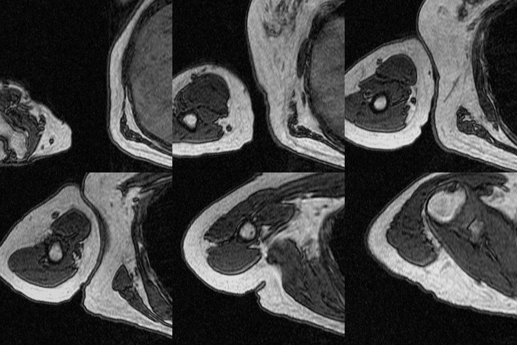
For my project so far, I have focused on a single MRI scan for one patient, which can be seen in the following video. This scan contains the patient’s torso as well as a portion of the arm, and 12 muscles were previously manually segmented in their entirety. The humerus was never segmented for this dataset, but because there is higher contrast between the bone and surrounding muscle as compared to between adjacent muscles, it is a good candidate for threshold-based segmenting techniques.

Figure 2: Dataset Video.

One tool I have tested on the MRI images to isolate the humerus is called the Flexible Learning-free Reconstruction of Imaged Neural volumes pipeline, also known as FLoRIN. FLoRIN is an automatic segmentation tool that uses a novel thresholding algorithm called N-Dimensional Neighborhood Thresholding (NDNT) to identify microstructures within grayscale images [4]. It does this by looking at groups of pixels known as neighborhoods, and it makes each pixel either white or black depending on if its intensity is less than or greater than a proportion of the neighborhood average. FLoRIN also uses volumetric context by considering information from the slices surrounding the neighborhood.
FLoRIN’s threshold is set to separate light and dark features, so the humerus must be segmented in two pieces because the hard, outer portion shows up as black on the scan while the inner part appears white. To generate the middle image in Figure 3, I inverted the set of MRI images and fed them through the FLoRIN pipeline, adjusting the threshold until the inner bone was distinct from the rest of the image. Next, I used FLoRIN to separate the three largest connected components, which are the red, blue, and yellow objects in the rightmost image. After sorting the connected components by area, I was able to isolate the inner part of the humerus, which is represented by the yellow component.

Figure 3: Original Image (left). Light Features as One Object (middle). Three Connected Components (right).

Another method I explored throughout my research was the use of a Convolutional Neural Network (CNN) to perform semantic segmentation, the process of assigning a class label to every pixel in an image. The script used to do this was inherited from Bo Lei of Carnegie Mellon University and was adapted to have additional functionality. To train a CNN to perform semantic segmentation, a set of the original images along with ground truth labels must be provided. A ground truth label is the actual answer in which each object in the image is properly classified, and this process is often done manually. However, because a network can be applied to a larger image set than it was trained on, manually segmenting the labels requires much less time as compared to manually segmenting an entire dataset. The CNN approximates a function that relates an input (the training images) to an output (the labels). The network parameters are initialized with random values and as it is trained, the values are updated to minimize the error. One complete pass through the training data is called an epoch, and at the end of each epoch the model performs validation with another set of images. Validation is the process in which the CNN tests itself to see how well it performs segmentation as it is tuning the parameters. Finally, after training is complete, the model can be tested on a third set of images that it has never seen before to give an unbiased assessment of its performance.

As stated previously, threshold-based techniques cannot be used to segment the individual arm muscles due to the lack of contrast, so I employed machine learning methods instead. For simplicity, I decided to start by training a network to only recognize one muscle class. I chose to begin with the bicep because of all of the upper arm muscles that have been segmented in this scan, it has the most distinct boundaries. This means that the network is being trained to identify two classes total, which are the bicep class and the background class. For this patient, there were 71 images containing the bicep, and I dedicated 59 for training, 10 for validation, and 2 for testing. For each set, I selected images from the MRI stack in approximately equally spaced intervals so that they each contained images that were representative of multiple sections of the bicep. After training a network using the SegNet architecture and the hyperparameters seen in Table 1, I evaluated its performance by segmenting the two full-size test images.

Table 1: Network Hyperparameters.

I created overlays of the CNN output segmentations and ground truth labels, and this can be seen below next to the original MRI image for the first test image. The white in the overlay corresponds with correctly identified bicep pixels, the green corresponds with false positive pixels, and the pink corresponds with false negative pixels. The overlay shows that the network mostly oversegmented the bicep, adding pixels where they should not be.

  Figure 4: Test Image 1 (far left). Ground Truth Label (middle left). NN Output (middle right). Overlay (far right).

In addition to assessing the network’s performance visually, I also calculated two metrics, which are the bicep Intersection over Union (IoU) and boundary F1 score. Bicep IoU is calculated by dividing the number of correctly identified bicep pixels in the CNN segmentation by the total bicep pixels present in both the ground truth label and the prediction. Boundary F1 score indicates what percentage of the segmented bicep boundary is within a specified distance (two pixels in our case) of where it is in the ground truth label. This network had a bicep IoU of 64.1%, and average boundary F1 score of 23.8%.

After training a network on the full-size images, I decided to try training on a set of cropped images to see if this would improve segmentation. The theory behind this test was to remove the majority of the torso from the scan because it contains features that have similar grayscale level as the bicep. This was done using a MATLAB script that takes a 250×250 pixel area from the same images used previously to train, validate, and test. This script as well as the one used to create the overlays were both inherited from Dr. Tiberiu Stan of Northwestern University. The coordinates were chosen so that the images could be cropped as much as possible without excluding any bicep pixels, which is portrayed in the set of videos below.

Figure 5: Cropped Images (left) and Labels (right).

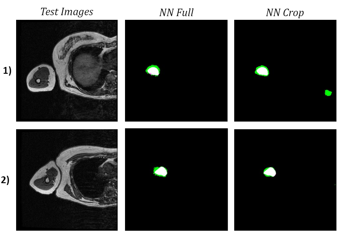
When comparing both networks’ bicep segmentations for the two test images, it is apparent that the network trained on cropped images predicted cleaner bicep boundaries. This is especially noticeable in the second test image because the green false positive pixels are in a much more uniform area surrounding the bicep. However, the network trained on cropped images had slightly a lower bicep IoU and boundary F1 score, which were 62.9% and 18.2% respectively. The cropped network also confused a feature in the torso with the bicep, which was not an issue for the network trained on full-size images.

Figure 6: Comparison of Test Image Segmentations.

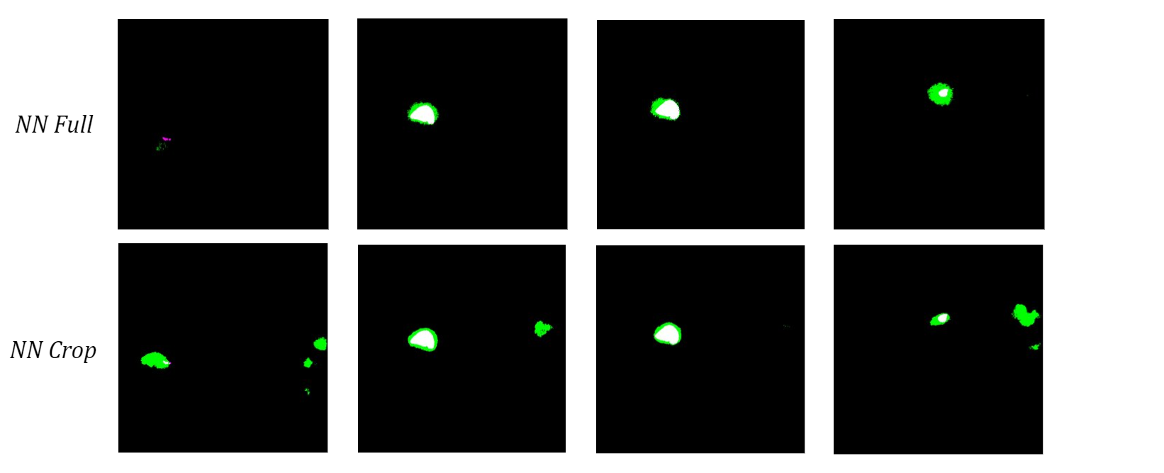
To see how the networks performed on a more diverse sample of MRI slices, I tested them both on the 10 validation images used in training. The neural network trained on the full-size images once again had a higher bicep IoU and often did a better job of locating the bicep. Although the cropped network typically had cleaner boundaries around the bicep, which is most obvious in the middle two images of the four examples below, it consistently misidentified extraneous features as the bicep.

Figure 7: Comparison of Validation Image Segmentations.

I hypothesize that the network trained on cropped images does this because it never saw those structures during training, so it cannot use location-based context to learn where the bicep is relative to the rest of the scan. Therefore, I anticipate that this actually caused more confusion due to the similar grayscale value of other muscles instead of minimizing it like I had hoped. Despite the current limitations, these results show promise for using machine learning methods to automatically segment upper arm muscles.

Moving forward, my main goals are to generate a cohesive segmentation of both parts of the humerus using FLoRIN as well as improve the accuracy of the bicep neural network. To segment the outer portion of the humerus, I plan to further tune FLoRIN’s thresholding parameters to separate it from the surrounding muscle. Once the segmentations are post-processed to combine the inner and outer parts of the bone, they have the potential to be used as labels for machine learning methods. As for the bicep neural network, I am in the process setting up a training set with multi-class labels that contain two additional upper arm muscle classes, namely the tricep and brachialis. My hope is that having more features as reference will improve the network’s ability to accurately segment the bicep boundary because these are the three largest muscles in the region of the elbow and forearm [2] and often directly border one another. Further improvement in the identification of the anatomical features within the upper arm has great implications for the future of rehabilitation. Knowledge of shape, size, and arrangement of these attributes can provide insight into how different parts are interrelated, and the ability to gather this information automatically has the potential to save countless hours of manual segmentation.


References:

  1. Adkins AN, Garmirian L, Nelson CM, Dewald JPA, Murray WM. “Early evidence for a decrease in biceps optimal fascicle length based on in vivo muscle architecture measures in individuals with chronic hemiparetic stroke.” Proceedings from the First International Motor Impairment Congress. Coogee, Sydney Australia, November, 2018.
  2. Holzbaur, Katherine RS, Wendy M. Murray, Garry E. Gold, and Scott L. Delp. “Upper limb muscle volumes in adult subjects.” Journal of biomechanics 40, no. 4 (2007): 742-749.
  3. Vidt, Meghan E., Melissa Daly, Michael E. Miller, Cralen C. Davis, Anthony P. Marsh, and Katherine R. Saul. “Characterizing upper limb muscle volume and strength in older adults: a comparison with young adults.” Journal of biomechanics 45, no. 2 (2012): 334-341.
  4. Shahbazi, Ali, Jeffery Kinnison, Rafael Vescovi, Ming Du, Robert Hill, Maximilian Joesch, Marc Takeno et al. “Flexible Learning-Free Segmentation and Reconstruction of Neural Volumes.” Scientific reports 8, no. 1 (2018): 14247.


Digitalize Argonne National Lab

Author: James Shengzhi Jia, Northwestern University, rising sophomore in Industrial Engineering & Management Science

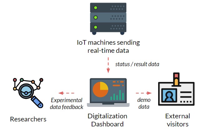
Imagine if you are a researcher here at Argonne, and you don’t have to go  upstairs downstairs all the time just to check the experiments that you are running — all you have to do is sit in front of the computer, monitor and control all of them in one system. Wouldn’t that be amazing?

Figure 1: Schematic of the project motivation

Before this internship, I couldn’t possibly imagine such a scenario. However, during the summer, I was working with my mentor Jakob Elias at Energy and Global Security Directorate and creating the beta infrastructure of the system that can connect and visualize real-time data from IoT machines at Argonne, and achieve automatic optimization of experiments.
The following short videos demonstrated the beta infrastructure that I created. It’s easy to navigate through the interactive map, and obtain key information about the areas, buildings, rooms and experiments that are of your interest. The dashboard is able to receive data from the local system, websites and also MQTT protocol. In the future, we plan to integrate various AI applications into the dashboard, so it becomes even smarter and grants researchers full control of their experiments right in their office. 
The second part of my work is testing the usability of this dashboard by using the metal 3D printing experiment in Applied Materials Department (AMD) as a test case. Let me give you a brief introduction of the experiment and their objective:  (Full explanation can be seen in Erkin Oto’s past post)

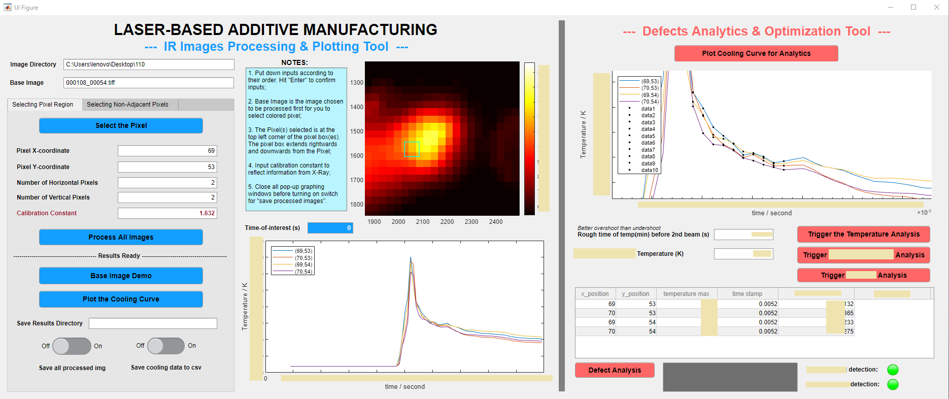
AMD researchers at Argonne utilize powerful laser beam, X-ray and IR to conduct metal 3D printing experiments, and the key objective is to characterize and identify the product defects. However, as X-ray machines (which are used to identify defects) are not as ubiquitous as IR machines, researchers at Argonne are exploring whether it’s possible to only use IR data to identify the defects in the products. 

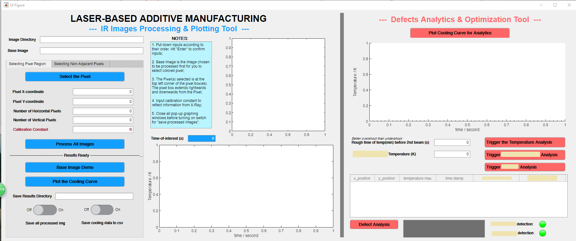
Firstly, as each experiment generates over 1000 IR images, I created a MATLAB software that speeds up the analysis of those images to just within 10 seconds. As shown below, the software works to transform an original black IR image to a fully colored image that researchers can select pixels-of-interest on.
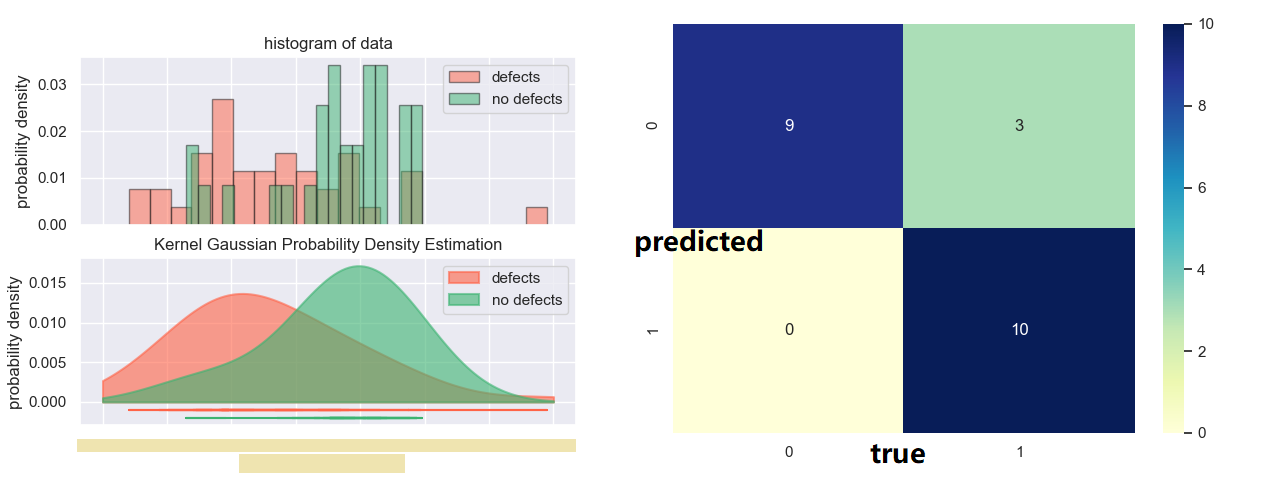
Secondly, additional to the processing tool, I also programmed an analytical tool (which can be seen below) to quantitatively analyze the defect / non-defect dataset. In the process, I came up with two original methods to investigate the correlation, and applied Kernel Gaussian PDF Estimation, Mann-Whitney U Test, and Machine Learning via logistic regressionBased on the original methods that I developed and therefore the machine learning model trained, the accuracy of the model reaches 86.3%, with p values for both method coefficient below 0.1. 
In the future, more efforts can be put into obtaining more accurate data, to improve the model. In a bigger picture, we can also explore about integrating applications like this into the dashboard, and achieve the digitalization of Argonne National Lab in the near future.
Disclaimer: all blocked image data are intended to protect the confidentiality of this project. Unblocked data are either trivial or purely arbitrary (such as ones in prototype dashboard).

Efficiency Optimization of Coherent Down-conversion Process for Visible Light to the Telecomm Range

Hello, my name is Andrew Kindseth and I am a rising junior at Northwestern University. I am majoring in Physics and Integrated Sciences. This summer I am working with Joseph Heremans, a physicist and material’s scientist who is working on the Quantum link and solid state defects that can be used as quantum bits. My project involves making optically addressable solid state defects compatible with existing fiber optic infrastructure. I am also attempting to improve on transmission distances. I expect to accomplish these goals using a process called difference frequency generation.
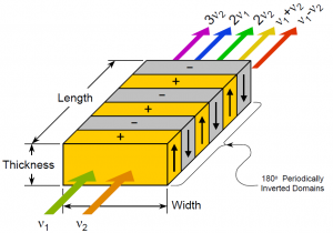
Difference frequency generation (DFG) is a three wave mixing process which takes place in a nonlinear crystal with a high X(2) term.  This term refers to the polarization response of the crystal to an electric field. When two waves of frequency w1, w2 pass through the crystal the X(2) term results in the generation of electric waves of 2w1,2w2, w1+w2, and w1-w2. A process called phase-matching can then be used to increase the amount of mixed light received from the process. The technique applied uses a process called quasi-phase matching, which is performed by using a crystale that has opposite orientations of the crystal lattice with specified period. This is called periodically poling. Our crystal is periodically poled with period such that we will generate photons of frequency w1 -w2 when performing our experiment.

Figure 1: Schematic of usage of periodically poled crystal for amplification of mixed waves. For input waves v1,v2 by selecting the poling we can preferentially generate photons through one of these mixing processes.

By controlling the relative energy densities of each of the respective frequencies of light, the conversion efficiency can be made to rise. This efficiency maximum occurs when one of the light frequencies is much stronger in power then the other. It is the lower power light that is converted efficiently. In the case of single photon pulses on one or either of the input light frequencies the conversion efficiency can become significant, and values of 80% have been demonstrated in experiments.
When one or both of the sources is pulsed the photon emission from the crystal is time correlated with the presence of both frequencies of light in the crystal. If energy imbalance and pulsing are combined, using a single photon pulse on one of the input frequencies, the efficiency and time correlation results in single photon down-conversion.
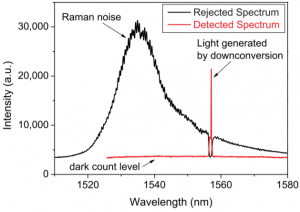
I am working on creating a down-conversion setup here at Argonne for downconversion of light from 637nm to 1536.4nm. The input light to the crystal will then be 637nm light and 1088nm light, with the 1088nm light having a vastly stronger power. The focus of my project is overall efficiency of the process, as well as minimizing the stray photons that may be detected through optical and spatial filtering. For spatial filtering I am using a prism pinhole pair in order to spatially separate the two input wavelengths from the output wavelength of 1536.4nm. This will require painstaking alignment and spectrum analysis. For optical filtering I am using a free space bragg grating. The bragg grating will filter out the Raman and Stokes-Raman noise that is much closer in wavelength to my output wavelength than the input wavelengths.
Figure 2: Spectrometer readings demonstrating the optical filtering ability and necessity of a Bragg grating. This figure was taken from Sebastian Zaske, Andreas Lenhard, and Christoph Becher, “Efficient frequency downconversion at the single photon level from the red spectral range to the telecommunications C-band,” Opt. Express 19, 12825-12836 (2011)

The relevance of this project arises from the field of quantum information. One of the goals of the field of quantum information is the creation of quantum information networks, as well as transmission of quantum information over large distances. One of the prime candidates as a carrier of quantum information is the photon. Photons are coherent over arbitrarily long distances in free space, and have low transmission loses. However, existing infrastructure for transport of photons only maintain the desirable properties of photons for photons of particular energies. The telecomm band is the region for which fiber optic cable has low transmission loss. For classical computers this frequency range is not problematic because the digital information is transmitted at the desired frequency. However, transmission of quantum information has only be performed with certain quantum bits (qbits). The qbits which are most technologically mature emit photons in the visible range. This is problematic, the emission wavelength of the qbits cannot be changed, and the transmission losses of visible light are prohibitive for the creation of long-distance communication or networks.
One of the most used photon emitting defects is the Nitrogen Vacancy center (NV center). The NV center is a qbit that emits photons of wavelength 637nm. Being able to down-convert the light from an NV center would allow NV centers to be used, with all of their intrinsic benefits, without crippling the ability to form large networks or send information. Initially, I am using a laser to simulate photons being emitted from the NV center, and trying to improve upon the total efficiency realized. Once the efficiency has been optimized with the laser imitator, the laser imitator will be replaced with an NV center.
Connections between nodes in quantum information networks are not the same as for classical networks. One method for forming a connection is to establish entanglement between nodes. This has been done over short distances between two of the same type of qbit. Our overall goal is twofold: to establish entanglement between two different types of qbits, and to do so over a longer distance than has been possible before. I expect that successful and efficient down-conversion will enable this to be acomplished.

Optimizing Neural Network Performance for Image Segmentation

Hi! My name is Joshua Pritz. I’m a rising senior studying physics and math at Northwestern University. This summer, I am working with Dr. Marta Garcia Martinez in the Computational Science Division at Argonne National Lab. Our research concerns the application of Neural Network based approaches to the semantic segmentation of images detailing the feline spinal cord. This, too, is part of a larger effort to accurately map and reconstruct the feline spinal cord with respect to its relevant features – namely, neurons and blood vessels.
Prior to outlining my contribution to this work, it’s worth introducing the terminology used above and, thereafter, illustrating why it fits the motivations of our project. Image segmentation, generally, is the process of identifying an image’s relevant features by distinguishing its regions into different classes. In the case of our cat spine dataset, we are currently concerned with two classes: somas, the bodies of neurons in the spine, and background, everything else. Segmentation can be done by hand. Yet, with over 1800 images collected via x-ray tomography at Argonne’s Advanced Photon Source, this task is all but intractable. Given the homogeneity of features within our images, best exemplified by the similarity of blood vessels and somas (indicated in Figure 1 by a blue and red arrow, respectively), traditional computer segmentation techniques like thresholding and K-means clustering, which excel at identifying objects by contrast, would also falter in differentiating these features.
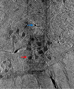
Figure 1: Contrast adjusted image of spinal cord. Blue arrow indicates blood vessel, while red arrow indicates soma.
Enter the Convolutional Neural Network (CNN), through which we perform what is known as semantic segmentation. Herein, a class label is associated with every pixel of an image. A CNN begins by assigning a trainable parameter, a weight, to each pixel in an incoming image. Then, in a step known as a convolution, it performs an affine operation on each submatrix of pixels in the image using a fixed scaling matrix called the kernel, which is then translated using another set of trainable parameters called biases. Convolutions create a rich feature map that can help to identify edges, areas of high contrast, and other features depending on the kernel used. Such operations also reduce the number of trainable parameters in succeeding steps, which is particularly helpful for large input images that necessarily subtend hundreds of thousands of weights and biases. Through activation functions that follow each convolution, the network then decides whether or not objects in the resultant feature map correspond to distinct classes.
This seems like a complicated way to perform an intuitive process, surely, but it begs a number of simple questions. How does the network know whether or not an object is in the class of interest? How can it know what to look for? Neural networks in all applications need to be trained extensively before they can perform to any degree of satisfaction. In the training process, a raw image is passed through the CNN. Its result – a matrix of ones and zeros corresponding respectively to our two classes of interest – is then compared to the image’s ground truth, a segmentation done by hand that depicts the desired output. In this comparison, the network computes a loss function and adjusts its weights and biases to minimize loss throughout training, similar to the procedure of least-squares regression. It takes time, of course, to create these ground truths necessary for training the CNN, but given the relatively small number of images needed for this repeatable process, the manual labor required pales in comparison to that of segmentation entirely by hand.
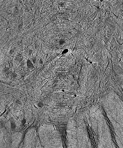
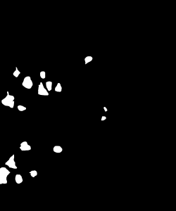
Figure 2: Cat spine image and its ground truth.

The question then becomes, and that which is of primary concern in this research, how can training, and the resulting performance of the CNN, be optimized given a fixed amount of training data? This question lives in a particularly broad parameter-space. First, there are a large number of tunable network criteria, known as hyperparameters (so as not to be confused with the parameters that underlie the action of the CNN), that govern the NN’s performance. Notably, these include epochs, one full pass of the training data through the network; batch-size, the number of images seen before parameters are updated; and learning rate, the relative amount parameters are updated after each training operation. For our network to perform exceptionally, we need to include enough epochs to reach convergence (the best possible training outcome) and tune the learning rate so as to meet it within a reasonable amount of time, while not allowing our network to diverge to a poor result (Bishop).
Second, we can vary the size of images in our training set, as well as the number of them. Smaller images, which are randomly cropped from our full-sized dataset, require a fewer number of trainable weights and biases, thus exhibiting quicker convergence. Yet, such images can neglect the global characteristics of certain classes, resulting in poorer performance on full-sized images. In choosing a number of images for our training set, we need balance whether or not enough data is present to affect meaningful training with oversampling of training data. To conclusively answer our project’s primary question without attempting to address the full breadth of the aforementioned parameter space, we developed the following systematic approach.
Prior to our efforts in optimization, we added notable functionality to our initial NN training script, which was written by Bo Lei of Carnegie Mellon University for  the segmentation of materials science images and, herein, adapted to perform on our cat spine dataset. It employs the PyTorch module for open-source accessibility and uses the SegNet CNN architecture, which is noteworthy for its rendering of dense and accurate semantic segmentation outputs (Badrinarayanan, Kendall and Cippola). The first aspect of our adaptation of this script that required attention was its performance on imbalanced datasets. This refers to the dominance of one class, namely background, over a primary class of interest, the somas. To illustrate, an image constituted by 95 percent background and five percent soma could be segmented with 95 percent accuracy, a relatively high metric, by a network that doesn’t identify any somas. The result is a network that performs deceptively well, but yields useless segmentations. To combat this, our additional functionality determines the proportion made up by each class across an entire dataset, and scales the loss criterion corresponding to that class by the inverse of this proportion. Hence, loss corresponding to somas is weighted more highly, creating networks that prioritize their identification.
We also include data augmentation capabilities. At the end of each training epoch, our augmentation function randomly applies a horizontal or vertical flip to each image, as well as random rotations, with fifty percent probability. These transformed images, although derived from the same dataset, activate new weights and biases, thereby increasing the robustness of our training data. Lastly, we added visualization functionality to our script, which plots a number of metrics computed during training with respect to epoch. These metrics most notably include accuracy, the number of pixels segmented correctly divided by the total number of pixels, and the intersection-over-union score for the soma class, the number of correctly segmented soma pixels divided by the sum of those correctly identified with the class’s false positive and negatives (Jordan). We discuss the respective significance of these metrics insofar as evaluating a segmentation below.
Table 1: Hyperparameters used in training.

After including such functionalities our interest turned to optimizing the network’s hyperparameters as well as the computational time needed for training. To address the former, we first trained networks using our most memory-intensive dataset to determine an upper bound on the number of epochs needed to reach convergence in all cases. For the latter, we conducted equivalent training runs on the Cooley and Bebop supercomputing platforms. We found that Bebop offered an approximately two-fold decrease in training time per epoch, and conducted all further training runs on this platform. The remainder of the hyperparameters, with the exception of learning rate, are adapted from Stan et al. who perform semantic segmentation on similar datasets in MATLAB. Our preferred learning rate in this case was determined graphically, whereby we found that a rate of 10-4 did not permit effective learning during training on large images, while a rate of 10-2 led to large, chaotic jumps in our training metrics.
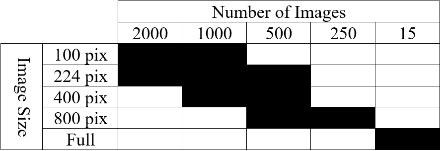
Table 2: List of tested cases depicting image size and number of images in training set.
Using such hyperparameters, listed in Table 1, for all successive training, we finally turned our attention to optimizing our networks’ performance with respect to the size of training images as well as the number of them used. Our initial training images (2300 by 1920 pixels) are very large compared to the size of images typically employed in NN training, which are in the ballpark of 224 by 224 pixels. Likewise, Stan et al. find that, despite training NNs to segment larger images, performance is optimal when using 1000 images of size 224 by 224 pixels. To see if this finding holds for our dataset, we developed ten cases that employ square images (with the exception of full-sized images) whose size and number are highlighted in Table 2. Image size varies from 100 pixels to 800 pixels per side, including training conducted on full-sized images, while image number varies from 250 to 2000. In this phase, one NN was trained and evaluated for each case.
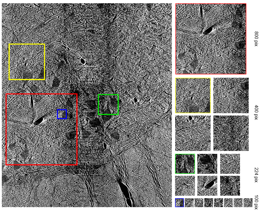
Figure 3: Detail of how smaller images were randomly cropped from full-sized image.
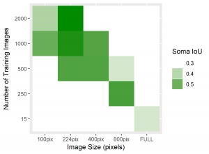
To standardize the evaluation of these networks, we applied each trained NN to two x-ray tomography test images. Compared to the 20+ minutes needed to segment one such image by hand, segmentation of one such 2300 by 1920 pixel image took averagely 12.03 seconds. Resulting from each network, we recorded the global accuracy, soma intersection-over-union (IoU) score, and boundary F-1 score corresponding to each segmentation. Accuracy is often high for datasets whose images are dominated by background, such is the case here, and rarely indicates the strength of performance on a class of interest. Soma IoU, on the other hand, is not sensitive to the imbalance in classes exhibited by our dataset. The boundary F-1 (BF1) score for each image is related to how close the boundary of somas in our NN segmentation is to that of the ground truth. Herein, we use a threshold of 2 pixels, so that if the boundary in our NN’s prediction remains within 2 pixels of the actual soma boundary, the segmentation would receive a 100% BF1 score (Fernandez-Moral, Martins and Wolf). Together with the soma IoU, these metrics provide a far more representative measurement of the efficacy of our network than solely global accuracy. For each network, we exhibit the average of these metrics over both test images in the table below, in addition to heatmaps for soma IoU and BF1 scores.
Figure 4: Heatmaps for BF1 and Soma IoU score for each case.
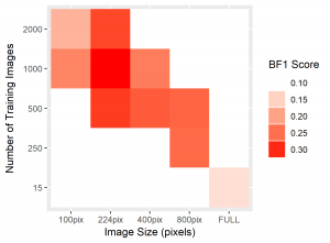

Table 3: Results from test image segmentations.
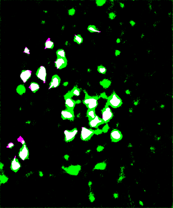
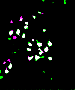
To visually inspect the quality of our NNs’ output, we overlay the predictions given by each network with the ground truth for the corresponding test image using a MATLAB script developed by Stan et al. This process indicates correctly identified soma pixels (true positives) in white and correctly identified background pixels in black (true negatives). Pink pixels, however, indicate those falsely identified as background (false negatives), while green pixels are misclassified as somas (false positives). We exhibit overlays resulting from a poorly performing network as well as those from our best performing network below.
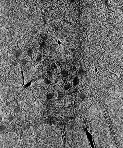
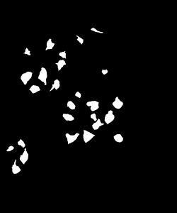
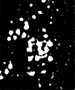
Figure 5: Top: raw test image (left) and test image ground truth (right). Bottom: NN (poorly performing) prediction (left) and overlay of prediction with ground truth (right).
The heatmaps above detailing soma IoU and BF1 scores visually represent trends in network performance with respect to image size and number. We recognize the following. The boundary F-1 score generally decreases when increasing the number of images in the training set. This is most likely due to oversampling in training data, by which resultant networks become too adept in performing on their training data and lose transferability that allows them to adapt to the novel test images. We recognize a similar trend in soma IoU. More so, network performance is seen to appreciate as we decrease the size of training images, until it reaches a maximum in the regime of 224 by 224 pixel images. The decrease in performance of networks trained on larger images may be explained by the lack of unique data. Despite a comparable number of training images, datasets of a larger image size are likely to have sampled the same portion of the original training images multiple times, resulting in redundant and ineffective training. The 100 by 100 pixel training images, on the other hand, are likely too small to capture the global character of somas in a single image given that some such features often approach 100 by 100 pixels in size. Hence, larger images may be needed to capture these essential morphological features. We find that highest performing network is that which was trained using 1000 images of size 224 by 224 pixels, exhibiting a global accuracy of 98.1%, a soma IoU of 68.6%, and a BF1 score of 31.0%. The overlay corresponding to this network shown in Figure 6 depicts few green and pink pixels, indicating an accurate segmentation.


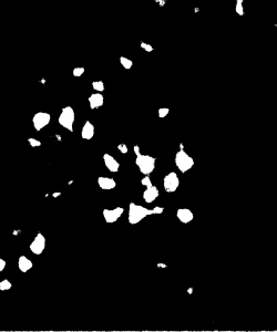
Figure 6: Top: raw test image (left) and test image ground truth (right). Bottom: NN (224pix1000num – best performing) prediction (left) and overlay of prediction with ground truth (right)
Ultimately, this work has shown that convolutional neural networks can be trained to distinguish classes from large and complex images. NN based approaches, too, provide an accurate and far quicker alternative to manual image segmentation and past computer vision techniques, given an appropriately trained network. Our optimization with respect to the size and number of images used for training has confirmed the findings of Stan et al. in showing that networks trained using a larger amount of smaller images perform better than those trained using full-sized images. Namely, our results indicate that 224 by 224 pixel images yield the highest performance with respect to accuracy, IoU, and BF1 scores. In the future, this work may culminate in the application of our best NN to the totality of the feline spinal cord dataset. With appropriate cleaning and parsing of the resultant segmentations, such a network could aid in novel 3D reconstructions of neuronal paths in the feline spinal cord.

References

Badrinarayanan, Vijay, Alex Kendall and Roberto Cipolla. “SegNet: A Deep Convolutional Encoder-Decoder Architecture for Image Segmentation.” IEEE Transactions on Patter Analysis and Machine Intelligence (2017): 2481-2495. Print.
Bishop, Christopher M. Pattern Recognition and Machine Learning. Cambridge: Springer, 2006. Print.
Fernandez-Moral, Eduardo, et al. “A New Metric for Evaluating Semantic Segmentation: Leveraging Global and Contour Accuracy.” 2018 IEEE Intelligent Vehicles Symposium (IV) (2018): 1051-1056. Print.
Jordan, Jeremy. “Evaluating Image Segmentation Models.” Jeremy Jordan, 18 Dec. 2018, www.jeremyjordan.me/evaluating-image-segmentation-models/. Website.
Stan, Tiberiu, et al. Optimizing Convolutional Neural Networks to Perform Semantic Segmentation on Large Materials Imaging Datasets: X-Ray Tomography and Serial Sectioning. Northwestern University, 19 June 2019. Print.